|
Кількість
|
Вартість
|
||
|
|
|||
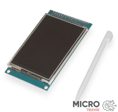
стилус
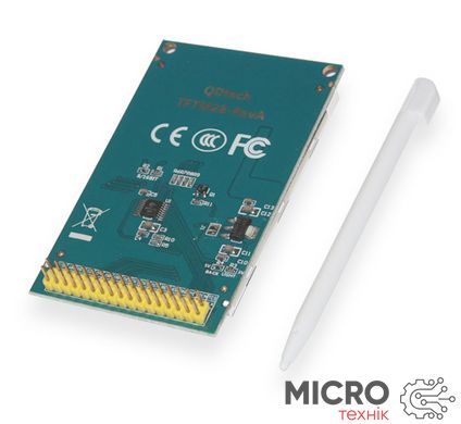
Контроллер ILI9325/ILI9331
| Pin Number | Mark | Description | Function |
| 1 | CS | LCD chip select signals | Active low |
| 2 | RS | Instruction / data register select | RS = 1: Instruction Register |
| RS = 0: data register | |||
| 3 | WR | Write Data | WR = 0, RD = 1 |
| 4 | RD | Reading data | WR = 1, RD = 0 |
| 5 | RESET | LCD reset | Low reset |
| 6 | D1 | Data Bus | Low 8: D1-D8 high 8: D10-D17 (8 mode when connected using high 8) |
| 7 | D2 | ||
| 8 | D3 | ||
| 9 | D4 | ||
| 10 | D5 | ||
| 11 | D6 | ||
| 12 | D7 | ||
| 13 | D8 | ||
| 14 | D10 | ||
| 15 | D11 | ||
| 16 | D12 | ||
| 17 | D13 | ||
| 18 | D14 | ||
| 19 | D15 | ||
| 20 | D16 | ||
| Twenty one | D17 | ||
| Twenty two | GND | Negative power supply module | Then the power ground GND |
| Twenty three | BLCNT | Backlight brightness adjustment | You can use IO or PWM to control the backlight brightness |
| Twenty four | VCC | Positive power supply module | QDtech module supports 5V and 3.3V power supply, a 3.3V power supply J1 shorted, 5V power supply must be disconnected J1 |
| 25 | VCC | ||
| 26 | GND | Negative power supply module | Then the power ground GND |
| 27 | GND | ||
| 28 | BLVCC | 3.3V positive external backlight | Short disconnect R3 R4, then use the onboard 3.3V power supply, do not take this pin; when the backlight may require a separate power supply connected to this pin through a 3.3V supply, then disconnect shorted R3 R4 |
| 29 | TP_SO | Touch panel SPI data output | Connected to the hardware or simulated SPI MISO |
| 30 | TP_SI | SPI data input touch panel | Connected to the hardware or simulated SPI MOSI |
| 31 | TP_IRQ | Touch panel interrupted | Detecting the touch panel is pressed, compared with low |
| 32 | NC | Vacant do not take | Vacant do not take |
| 33 | TP_CS | The touch panel chip select signals | Link to hardware or simulated SPI's CS, active low |
| 34 | TP_SCK | Touch panel SPI clock signal | Connected to the hardware or simulated SPI SCK |


